
Raztech Hall Effect Current Sensors
These guys gave me some samples a few years ago when I was working on a commercial project as a consultant Hall Effect Sensors
Its a nice way to measure current as there is no shunt to reduce the voltage which is in short supply on RC models.
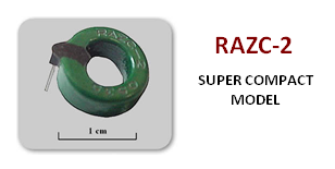
This example is like the one I have for high range current like in yellow boat. You 20 mV change in the output signal for each amp.
Therefore the range should be a 2 Volts delta for 100 amps going through the wire.
The resolution on a Arduino 10 bit converter give a current resolution of 4.8828125 mV per bits so 409 values representing the 2 volt output change for 100 amps, so approximately 250mA per bit which should be fine when measuring such a chunky supply current.
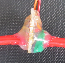
Notice the chunky wire I fitted there is no other filtering so it will be interesting to see if we need to do some work in the software to filter out any noise.
The whole thing is then potted with hot glue to protect it and a gold connector soldered to the end of the thick cable.
Next I have a lower range version which should be good for my FPV plane.
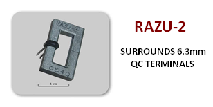
This device is intended to allow the user to add as many turns as needed to get the range they want, each turn doubling the gain
The one I have has 5 turns of fairly chunky 4 mm² solid copper should be good for the job.
 This device has a gain of 55mV per amp giving a 36 Amp working range, and a resolution of 88 mA per bit with the maximum output at 5 volts which is 1024 bits in the Arduino. By the way I should point out that these devices on a 5 volt rail will sit around 2.5 volts with no current flowing, so at a 2 Volt delta the out put should be around 4.5 V. I will test this and see how good it is however I don't think it matters if the top end is clipped of as you seldom operate at maximum current for very long in practice.
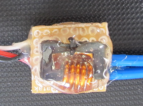
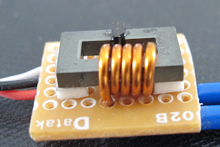
Here it is all potted up with decent sized cables soldered to the ends of the solid copper turns.
I have tested both of these and they work as described measured against my HobbyKing HK-010 Wattmeter & Voltage Analyzer which is turning out to be a handy tool. Going to need a scope next maybe next year.


Notice the chunky wire I fitted there is no other filtering so it will be interesting to see if we need to do some work in the software to filter out any noise.
The whole thing is then potted with hot glue to protect it and a gold connector soldered to the end of the thick cable.
Next I have a lower range version which should be good for my FPV plane.
This device is intended to allow the user to add as many turns as needed to get the range they want, each turn doubling the gain
The one I have has 5 turns of fairly chunky 4 mm² solid copper should be good for the job.

Here it is all potted up with decent sized cables soldered to the ends of the solid copper turns.
I have tested both of these and they work as described measured against my HobbyKing HK-010 Wattmeter & Voltage Analyzer which is turning out to be a handy tool. Going to need a scope next maybe next year.
Some test data up to 10 amps calibrated against the HK-010 Wattmeter
Raztec data sheet info
Comments
Nice
will take a look I only used these because I had them is stock from an old project
What about Allegro MicroSystem's Hall effect current sensors?
I see its a shunt type sensor, so there is some energy used as heat in the resistor these devices.
The difference is that the raw output on the Raz is offset at arround half the supply voltage so you can add some analogue circuitry to null that out, or if do it in software.
One thing teh raw signal from the 100 A Raz is 0.01V per amp so with a 10 bit analogue input you would have around 0.5A resolution. As I say adding an analogue circuit to calibrate teh device to 0 to 5V for an Arduino would improve the resolution to around 0.1Amps
Test Data
@ Randy
AttoPilot voltage and current sensor is available at Spakrfun
https://www.sparkfun.com/products/9028
These hall effect sensors look like good alternative if you have a way to calibrate the output.
The output is just a voltage proportional to current so if that's what the Otto does then I suppose it is an alternative I am not familiar with the Atto (otto)
Ok, so I guess it's an alternative to the Atto (Otto?) current sensor which for some reason i'm unable to find in the diydrones store.