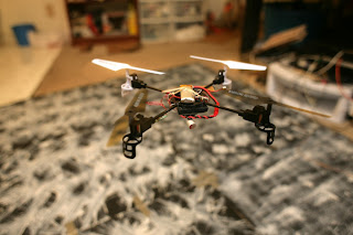
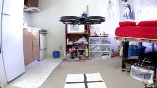
The copter flies away & returns to the starting point at 2 different altitudes, using only optical flow odometry for position & sonar for altitude. The fact that it landed at nearly the takeoff position was probably coincidence, but optical flow has proven very accurate in a 30 second hover. It may depend more on time than movement.
For the 1st time in many years, the entire autopilot was on board. Only configuration parameters are still stored on the ground station.
The takeoff is hard coded for a certain battery charge. This battery may have put out a lot more than the battery it was hard coded for, causing it to bounce during the takeoff. Nothing optical flow guided besides the AR Drone has been shown doing autonomous takeoffs & landings. It takes a lot of magic.
It was a lot more stable than the ground based camera. Ground based vision had a hard time seeing the angle of movement, relative to the copter. Optical flow has precise X & Y detection in copter frame.
How long can they stay in bounds? The mini AR Drone did surprisingly well, compared to the commercially successful AR Drone. The degradation was reasonable for a camera with 1/3 the resolution & 2/3 the frame rate. It's not likely to get more accurate. The mane problem is glitches in the Maxbotix.
Optical flow can hover for around 90 seconds at 0.5m before slipping off the floor pattern. Above 1m, it slips off after 1 minute. At 1.5m, it slips off after 30 seconds. The Maxbotix falls apart at 1.5m over posterboard.
The mane requirement in optical flow is the angular motion needs to be very accurately eliminated or it won't work at all. Using the IMU gyros works well. This is done by adjusting a 2nd pair of gyro scale values until rotating the camera doesn't produce a position change.
The heading & altitude need to be factored in when integrating optical flow or it won't accurately calculate position. The academic way to convert pixels to ground distance involves a tan of the pixel shift to compensate for parallax, then multiply by the altitude. The pixels are so small, the parallax was neglected & the pixel shift was just multiplied by altitude.
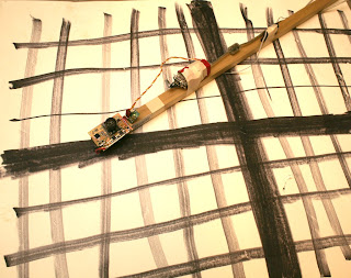
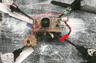
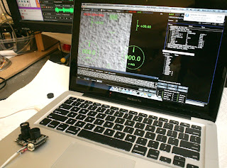
Optical flow initially needs to be tested on something like this:
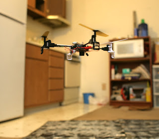
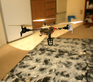
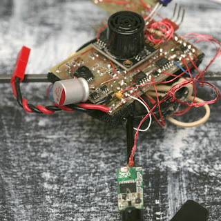
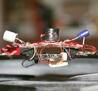
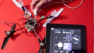
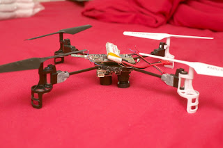
To gain enough confidence & calibrate it enough to start integrating it on this:
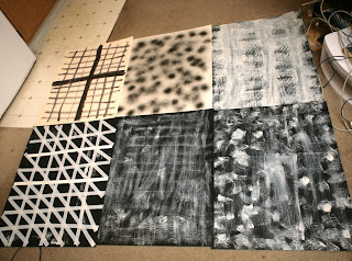
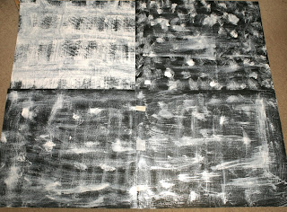
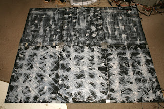
A lot of energy went into finding the optimum floor pattern.
So the optimum pattern seems to be random splotches of paint with dry brushing in a grid. Too much brushing makes it too smooth. A few gallons of toner would be nice. A laser printer could get the optimum fractal pattern perfect.
For all the energy going into making robots navigate human environments, there's no pondering of the idea of making human environments navigable for robots. Floors with optical flow patterns would be a lot easier than LIDAR.
Straight lines of featureless tape were the worst. It seems to rely on texture of the paint up close, while painted patterns far away. The only way to get a pattern big enough to fill the flying area with enough reflection for sonar is paint on a plastic drop cloth.
The worst patterns require a higher minimum motion. The best patterns cause the least minimum motion to be detected. The pattern affects the outcome more than the frame rate or resolution.
There was a lot of AR Drone testing, revealing its optical flow camera is 320x240 60fps, revealing the limitations of optical flow.
Long & boring video documenting interference between wifi & the Maxbotix MB1043, the world's most temperamental sensor. Some orientations do better than others. The Maxbotix & wifi wouldn't be very useful on any smaller vehicle.
A totally random orientation of wire & dongle was required. Wire orientation, wire insulation, dongle orientation, dongle distance all determined whether the Maxbotix died. Any slight movement of the wire breaks it.
The automatic takeoff & altitude hold were extremely accurate. The 10Hz update rate wasn't as problematic as feared.
It still needs an external RC filter to filter the power supply. You'd think they would have found a way to store the calibration data on the flash or make a bigger board with integrated power filter to generate the best readings.
The Maxbotix still requires a manual trigger to range at its maximum rate of 10Hz, but it repeats the same value if triggered at less than 25Hz. It needs to be triggered at 50Hz to output 10Hz of unique data.
Flying it manually with the tablet is reasonably easy.
The mini AR Drone has an MPU9150 read at 1100Hz for the gyros, 125Hz for the accelerometers & mag. The PWM is 2000Hz. The IMU needs liberal foam padding or the attitude readout drifts too fast.
It turns out USB host on the STM32F407 interferes with I2C, so you can't read the IMU when wifi is on. It has nothing to do with RF interference. The IMU has to be driven off a secondary microprocessor & the data forwarded on a UART. It needed a 400khz UART to transfer the readings fast enough.
There's at least 0.5ms of extra delay to get the readings from the I2C breakout processor to the mane processor. The I2C interface itself has at least 0.4ms of delay to get the voltage from the gyro. In total, it could take 1ms for a motion to be detected. Such is the sacrifice of reading out an IMU on I2C. The delays from movement to digital reading are what make instability. It's not unlike the AR Drone, which has a second microprocessor read the I2C sensors.
The electronics with wifi use 300mA. Wifi sends 2 megabits, manely consisting of the optical flow preview video. Star grounding & star power supply were required for anything to work. Having everything except the motors behind a 3.3V regulator & 1000uF of capacitance was required.
Wifi was especially sensitive to voltage glitches, making running on a 4.2V battery with lousy MIC5205 regulators extra hard. The MIC5353 would be a much better experience.
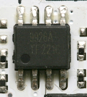
After years of dicking around with charge pumps, pullup resistors, & BJT's to turn on MOSFETs that require 5V to turn on, finally got around to probing the Syma X1's board. It uses a MOSFET that turns on at 2.5V, the 9926A. The 9926A is an extremely popular dual MOSFET made by many manufacturers.
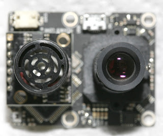
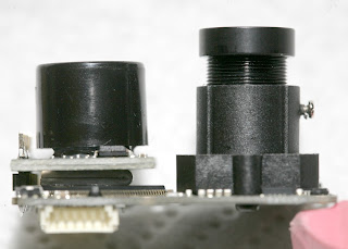
The electronics weigh around the same as a PX4Flow, except using the PX4Flow would have required another board in addition to it. The PX4flow was ruled out because of the weight & the size being too big to fit anywhere.
PX4Flow weight: 17.5g
With the PX4Flow connected to USB & Qgroundcontrol fired up on a Mac, it was immediately clear that it had a very long, sharp, macro lens, allowing it to resolve texture from far away.
Setting it to low light mode produced a noisier image. In any mode, the position updates came in at 100Hz, despite the sensor capturing 200Hz.
It didn't need any calibration. Just connect it & it outputs Mavlink position packets. The lens was already focused. It outputs packets at 100Hz on USART 3 but not USART2. It seems to run as low as 3.3V at 120mA. Below that, current drops & LEDs start going out. Above that until the 5V maximum, current is constant.
Most of what the PX4Flow does was redone on a new board, with the TCM8230. The autopilot was implemented on the same chip. The optical flow only does single pixel accuracy, 42fps. It crops to get a similar narrow field of view. It scans a 96x96 area instead of the PX4flow's 64x64. The scan radius is 8 pixels instead of the PX4flow's 4.
It requires a more detailed surface than the PX4Flow. The optimum combination of camera contrast, motion distance, frame rate, & scan radius dictated the camera run at 320x240. Running a higher frame rate or resolution made the camera less sensitive & blurrier in the X direction.
Also, the PX4flow uses a histogram of the motion vectors. Found better results from a straight average of the motion vectors.
Assembly language made an incremental improvement in the scanning speed, but the mane limitation still seemed to be memory access. The scanning area & scan radius would probably have to be slightly smaller in C.
The Goog couldn't find any examples of vectored thumb inline assembly, so it was a matter of trial & error. The STM32F4 programming manual, inline assembler cookbook, & STM32 Discovery firmware are your biggest allies in this part of the adventure.
It turns out there are no NEON instructions in thumb mode. Thumb mode has yet another set of vectored instructions with no special name.
For the 1st time ever, it's the inline assembly language absolute difference of an 8x8 macroblock:
#define ABSDIFF(frame1, frame2) \
({ \
int result = 0; \
asm volatile( \
"mov %[result], #0\n" /* accumulator */ \
\
"ldr r4, [%[src], #0]\n" /* read data from address + offset*/ \
"ldr r5, [%[dst], #0]\n" \
"usada8 %[result], r4, r5, %[result]\n" /* difference */ \
"ldr r4, [%[src], #4]\n" /* read data from address + offset */ \
"ldr r5, [%[dst], #4]\n" \
"usada8 %[result], r4, r5, %[result]\n" /* difference */ \
\
"ldr r4, [%[src], #(64 * 1)]\n" /* read data from address + offset*/ \
"ldr r5, [%[dst], #(64 * 1)]\n" \
"usada8 %[result], r4, r5, %[result]\n" /* difference */ \
"ldr r4, [%[src], #(64 * 1 + 4)]\n" /* read data from address + offset */ \
"ldr r5, [%[dst], #(64 * 1 + 4)]\n" \
"usada8 %[result], r4, r5, %[result]\n" /* difference */ \
\
"ldr r4, [%[src], #(64 * 2)]\n" /* read data from address + offset*/ \
"ldr r5, [%[dst], #(64 * 2)]\n" \
"usada8 %[result], r4, r5, %[result]\n" /* difference */ \
"ldr r4, [%[src], #(64 * 2 + 4)]\n" /* read data from address + offset */ \
"ldr r5, [%[dst], #(64 * 2 + 4)]\n" \
"usada8 %[result], r4, r5, %[result]\n" /* difference */ \
\
"ldr r4, [%[src], #(64 * 3)]\n" /* read data from address + offset*/ \
"ldr r5, [%[dst], #(64 * 3)]\n" \
"usada8 %[result], r4, r5, %[result]\n" /* difference */ \
"ldr r4, [%[src], #(64 * 3 + 4)]\n" /* read data from address + offset */ \
"ldr r5, [%[dst], #(64 * 3 + 4)]\n" \
"usada8 %[result], r4, r5, %[result]\n" /* difference */ \
\
"ldr r4, [%[src], #(64 * 4)]\n" /* read data from address + offset*/ \
"ldr r5, [%[dst], #(64 * 4)]\n" \
"usada8 %[result], r4, r5, %[result]\n" /* difference */ \
"ldr r4, [%[src], #(64 * 4 + 4)]\n" /* read data from address + offset */ \
"ldr r5, [%[dst], #(64 * 4 + 4)]\n" \
"usada8 %[result], r4, r5, %[result]\n" /* difference */ \
\
"ldr r4, [%[src], #(64 * 5)]\n" /* read data from address + offset*/ \
"ldr r5, [%[dst], #(64 * 5)]\n" \
"usada8 %[result], r4, r5, %[result]\n" /* difference */ \
"ldr r4, [%[src], #(64 * 5 + 4)]\n" /* read data from address + offset */ \
"ldr r5, [%[dst], #(64 * 5 + 4)]\n" \
"usada8 %[result], r4, r5, %[result]\n" /* difference */ \
\
"ldr r4, [%[src], #(64 * 6)]\n" /* read data from address + offset*/ \
"ldr r5, [%[dst], #(64 * 6)]\n" \
"usada8 %[result], r4, r5, %[result]\n" /* difference */ \
"ldr r4, [%[src], #(64 * 6 + 4)]\n" /* read data from address + offset */ \
"ldr r5, [%[dst], #(64 * 6 + 4)]\n" \
"usada8 %[result], r4, r5, %[result]\n" /* difference */ \
\
"ldr r4, [%[src], #(64 * 7)]\n" /* read data from address + offset*/ \
"ldr r5, [%[dst], #(64 * 7)]\n" \
"usada8 %[result], r4, r5, %[result]\n" /* difference */ \
"ldr r4, [%[src], #(64 * 7 + 4)]\n" /* read data from address + offset */ \
"ldr r5, [%[dst], #(64 * 7 + 4)]\n" \
"usada8 %[result], r4, r5, %[result]\n" /* difference */ \
\
: [result] "+r" (result) \
: [src] "r" (frame1), [dst] "r" (frame2) \
: "r4", "r5" \
); \
\
result; \
})

Comments
Jack,
This implies that you got the MPU9150 working for both rates and magnatometer.... last time you posted on this subject it was giving you problems....
Care tto share the code/scret of unlocking the MPU9150?
It's ironic that you will probably end up making your fortune as an artist. I think that your floor pattern series should be hanging on a gallery wall.
Hey Jack impressive as always, what would happen if you used sonar for altitude and optical flo off the walls for position or vise versa . Have a Great Day!
Great work! I like your comment about making environments more robot friendly as an easier approach than the other. The opposite would be true for environments wanting to be extra secure. I wonder if there are optimum textures for confusing robotic vision systems?
As usual Jack, Phenomenal.
I have a PX4 flow on order for my PX4 and you have just provided more real information on the topic than I have seen anywhere else.
Thank You.
You never disappoint me Jack. Everything you do with robotics is amazing and one of a kind! You truly are a genius in the way you overcome technical issues to bring us craftsmanship seen nowhere else.
In general I was never muchimpressed with the AR drone optical flow which I have since upgraded to px4+flow so I will see how that compares.
Mainly it seemed to me that the stock ar drone optical likes the kinds of surfaces the sonar does not like such ar carpets etc, but it never seemed to track on tarmac for example.